Raw EEG data contains a lot of ‘noise’ from many different sources that contaminate the ongoing data. The simplest way to remove a large section of noise is to exclude waveforms that are oscillating at a given frequency that we know cannot be generated by the brain or we know is highly likely to be generated by a source outside the brain. This process is called filtering. We know small currents generated by sweat or electrode movements will cause low frequency changes or ‘drift’ in the data. We also know the electrical field generated by power outlets and electrical equipment in the room oscillates at approximately 50 Hz (in the UK). We can therefore apply a filter that will remove low frequency changes to remove drift and high frequency oscillations to remove a ‘mains hum’.
Although conceptually, relatively straightforward,
There are some terms used in filtering that are useful to know:
- Low pass (aka high cut off) = A filter at which all frequencies below the specified frequency are preserved in the data.
- High pass (aka low cut off) = A filter at which all frequencies above the specified frequency are preserved in the data.
- Band pass (aka pass band) = A filter which preserves frequencies within a specific range.
- Band stop (aka stop band) = A filter which removes frequencies within a specific range.
- Notch filter = A form of band stop filter that usually operates within a narrower frequency range.
How
We are now going to filter the dataset that you have already down sampled. To do this in EEGLAB click:
-> Tools
  -> Filter the data
    -> Basic FIR filter (new, default)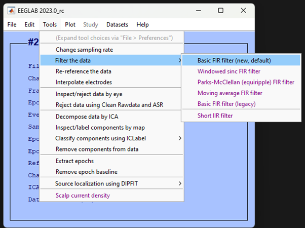
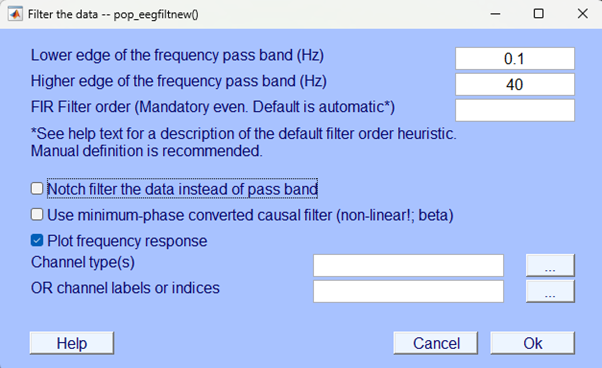
In the window that pops up enter 0.1 for the Lower edge of the frequency pass band (Hz) and 40 for the Higher edge of the frequency pass band (Hz).
Accept the defaults (i.e., leave blank) other sections and click Ok:
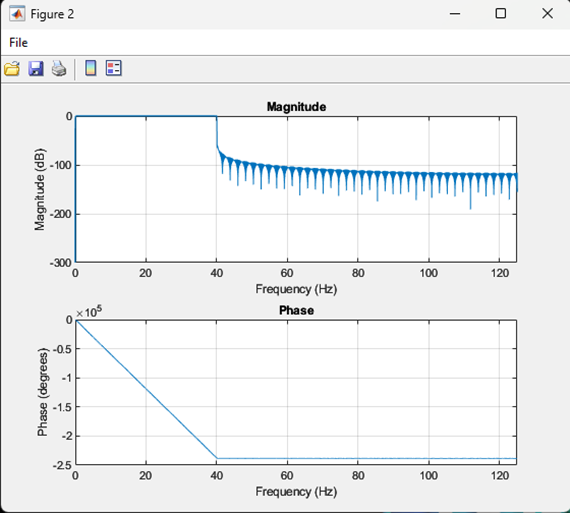
Before the filtering is completed you should see a graph pop-up that represents the magnitude of the filter as a function of frequency and a second graph showing its phase. The top graph is a representation of the strength of the effect of the filter for the frequency distribution of the EEG - you should see little effect between 0.1 and 40 Hz (line at zero) and then a sharp increase at 40 Hz. The bottom graph depicts the phase shifting effect of the filter on the EEG signal. In simpler terms, phase describes the relative timing of the waveforms that make up the signal. Effectively, the bottom graph tells you how “shifted” each frequency component is in comparison to a reference. This isn’t too important to understand for our practical purposes but it is important to note that filtering does have an effect on our signal of interest - albeit a small one. The graphs should look like this:
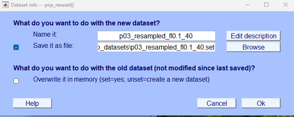
 Your filtering isn’t yet finished. Wait till the pop-up gives you the opportunity to save the dataset, give the file a name and save it in a location with the previous files. Here we’ve labelled the file
 p03_resampled_fl0.1_40 - this should allow us to easily identify what processing steps have been applied to this data
More eye-balling
Now, let’s visually inspect the data to see what it looks like after filtering. You want to plot the continuous data and scroll through it, if you don’t remember how to do that you can check back to the Eye-balling chapter, specifically, Plotting continuous data.
Your newly filtered data should look a little like the image below.
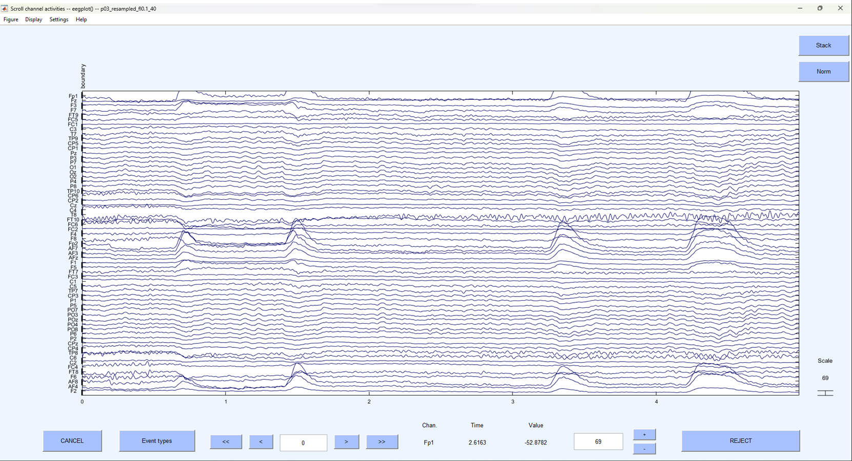
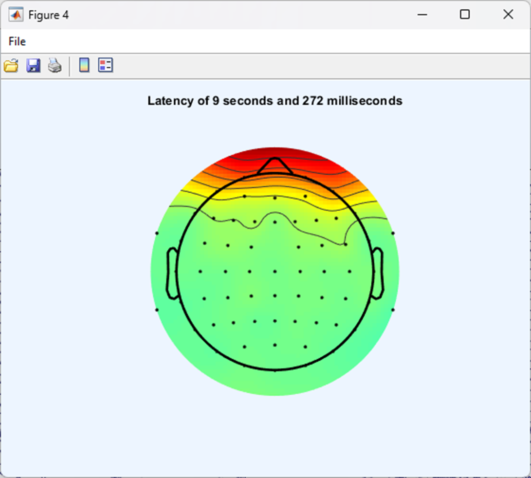
As you did when initially visually examining the data play around with the settings and explore further along the continuous data. You should now be able to identify individual electrodes and the EEG activity associated with them. If you right click on the data EEGLAB will plot the data ‘topographically’ - meaning the data at a specific time point (wherever you clicked on the plot) will be displayed in colour and mapped onto the scalp surface. A little like this:
Events
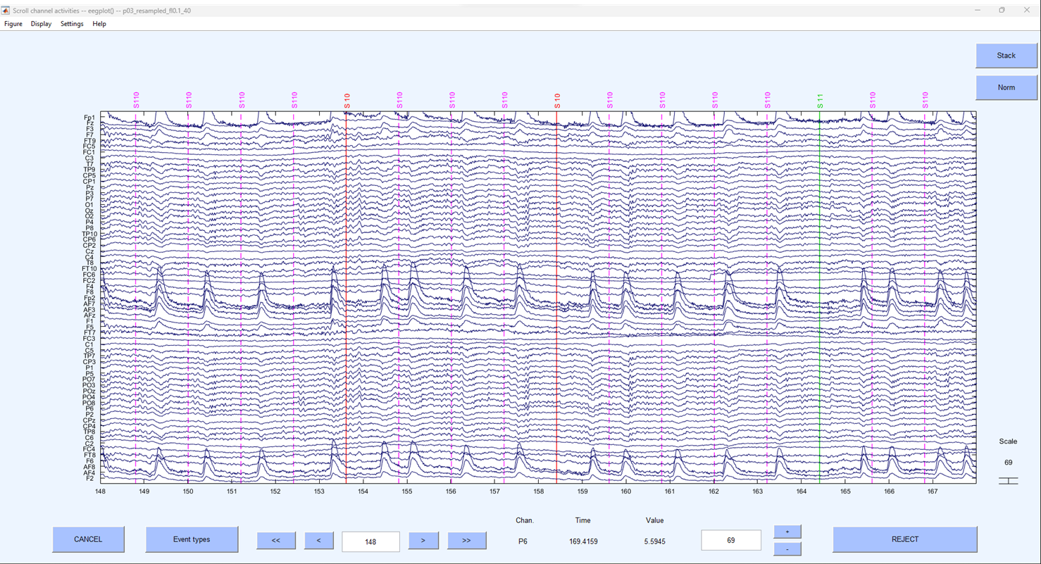
If you scroll along far enough in the EEG data you may see some coloured vertical lines labelled with letters and numbers - a little like the figure shown below. These are commonly referred to as ‘events’ or ‘markers’. They donate a specific point in time when something happened during the experimental protocol. So, for example, an event might be when a participant was presented with a stimulus or when the participant made a response on the keyboard. Given that our data is from the Jones & Ward (2019) paper - events might be when a participant was shown an object in a rhythmic condition, or it could represent stimuli presented arrhythmically.
Test yourself
Question 1 | What effect will a 10 Hz high pass filter have on the data?
Question 2 | What is the name of the plot that graphically represents EEG activity for a specific point in time by mapping it on the scalp?